Workshop : SV650 Race Wire Harness 2nd Gen 03-06
This post has already been read 60616 times!
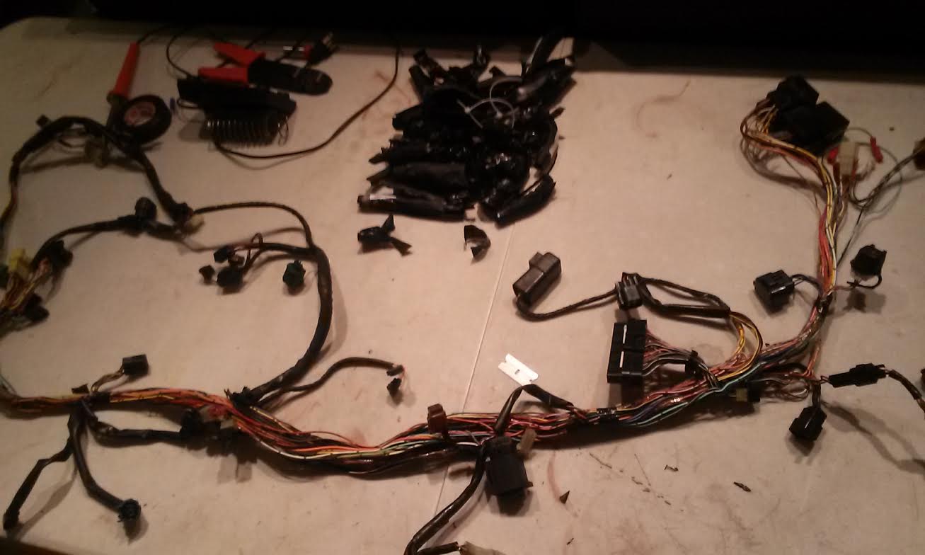
We are going to take a stock wire harness from a 2005 SV650 and turn it into a full blown race harness with only the bare minimum. We will start by removing the little things and when you feel that you have removed all that you wish to remove then you can stop following. To start we will start by stripping the harness’s protection. This way we can actually remove the wires for the lights etc instead of just cutting off the connectors. While you are working on your harness it is very important to keep a wire harness diagram in front of you so you can trace wires on your actual harness and on the diagram. GET STOCK SV650 COLOR WIRE HARNESS DIAGRAM HERE (this is for a 2003, but will basically work for 03-06, there are a few differences but you can spot them and realize they aren’t that important).
A few things to keep in mind while you are modifying your SV650’s wire harness for racing.
- Only remove what you don’t want or don’t think you’ll need.
- Black/Red Tracer wire is HOT, meaning power is always flowing through it, so if you are looking to add lap timer/gps/transponder, you may want to use this wire but add a switch.
- Black/White Tracer wire is GROUND, meaning make sure this properly grounded to the frame. Just like B/R wire for your extra, use this wire as your ground.
- Orange/White Tracer wire should only have power flowing AFTER the ignition toggle has been set on. This wire if very important as it carries power to your starter, ignition coils, and fuel pump.
- Solder, heat wrap, and use high quality electrical tape.
We will call this “Stage 1” See the Diagram below.
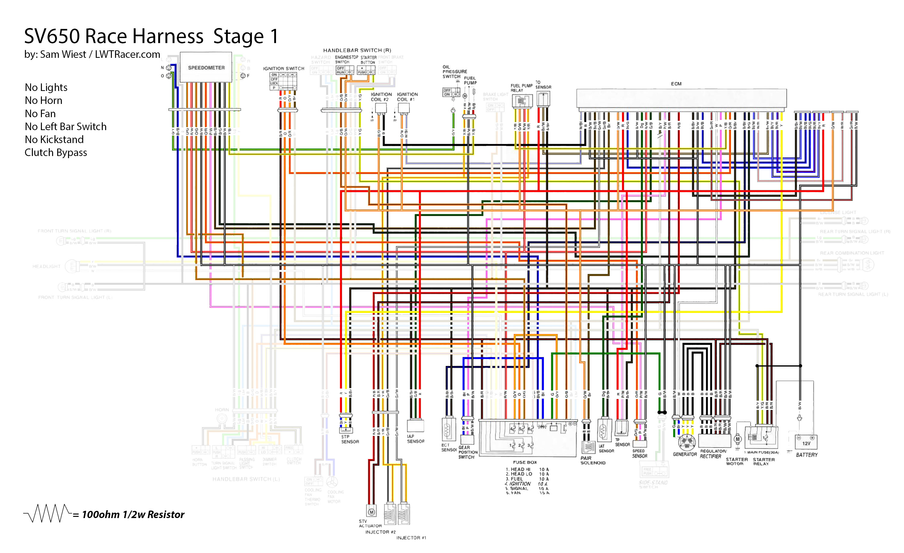
First step is to remove what no race bike needs (unless you’re doing 24hr endurance races) and that is the lights, light switches, left bar control, and the horn. So by either looking at the wire diagram or the sv650 harness in front of your face, you can spot the wires you dont needs. Except for the clutch by pass, Start with each connector, trace the wires back to their sources, SNIP! This is the easiest part and less stressful part of this entire process. Almost anything after this could potentially stop the bike from running correctly or a throw dealer codes.
With removal of the left bar switch we will need to a clutch bypass on our SV650 wire harness. At the ECU you will see a B/Y (Black/Yellow Tracer) wire coming out, you can snip this. At the main fuse, the B/Y wire coming out will be cut a few inches from the connector, this wire needs to be connected to a ground wire or the ground on the battery. Hopefully the graphic below helps you imagine the SV650 Clutch Bypass.

SV650 Kick Stand/Side Stand Delete
Kick stand switch is next. This is a Green wire which needs to be connected to a ground wire right at the connector.. If you follow this article to the end, you don’t even need to worry about this as we will be removing the fuse box completely which is where the green wire comes from.
You cannot just find something you don’t want and remove the wires. The Pair Solenoid, Tip Over Switch (TO), and Ignition all need 100ohm 1/2w resistors soldered in. Other things like the Fan, left bar switch, engine coolant sensor (ECT), and brake light switch can just be pulled out.
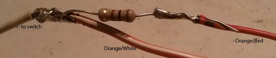
Most racers do not want to deal with a key on their bike. The ignition delete mod is a very easy one. You can use my “keep in mind” from earlier up in the article. Black/Red is HOT! Orange/White NEEDS POWER! We get Orange white it’s power through the switch. Orange/Black needs to get power from the Black/Red so we connect the two, you can either do this at the fuse box or up at the switch. I like to do it at the switch since my ending harnesses do not have a fuse box. Now that we have the hot wire (b/r) getting power into the switch via O/B, Orange/White should have power coming out of the switch turning on our mean machine. The second step of this process is tricking the ECU into thinking that the OEM key switch has been turn on. The Orange/Red wire from the ECU is our focus here. It gets connected to the Orange/White wire coming out of the new ignition switch (now a hand control). But, it’s not that easy as we need to trick the ECU, which is when we solder in a nice 100ohm 1/2w resistor.
-NOTE: If you are running gauges, the ORANGE wire from the original ignition switch connector needs to be soldered into the ORANGE/WHITE coming from kill switch as you can see in the “stage 2” diagram above.
| SV650 PAIR Solenoid Delete Removing the PAIR system is one of the most common things on most race bikes. We might as well remove the wires, right? A very simple process for this one. Solder in a 100ohm 1/2w resistor between the brown wire and the orange/white wire. This will eliminate the Fi light/Code from showing. 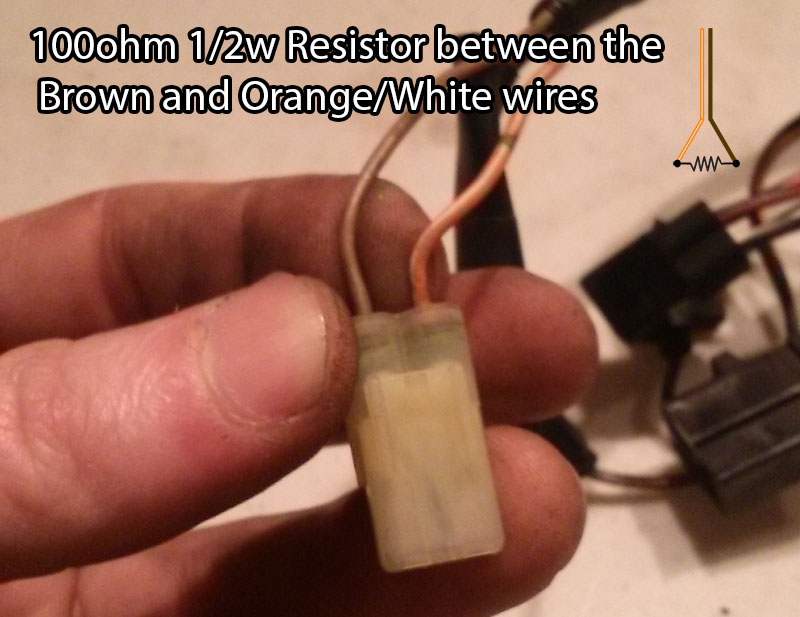 |
SV650 Tip Over Switch Delete I like to remove the SV650 Tip Over Sensor as to eliminate one more thing to stop your race bike from making the grid. This step requires two 100ohm 1/2w resistors. There are three wires in the sv650’s tip over sensor, Red, Brown/White Tracer, and Black/Brown Tracer. A resistor needs to be placed between the Red and Br/W wire and between the B/Br and Br/W wire. See the Stage 2 diagram below.  |
Below we have the wire diagram for a total loss bare minimum sv650 race wire harness. No gauge, no charging system, just the bare essentials for your bike to run. As you can see there is a big difference between this stage 3 diagram to the previous stage 2. You can do something in between. Most will prefer to keep the gauge cluster, I personally do not look at it but the stock sv650 gauge can come in very handy when you need to diagnose an issue. Another thing you will notice is there is no fuse box or fuses, if this does not sit well with you, you can add a fuse between the Black/Red wire and the Orange/Black wire before the Orange/Black wire enters the on/off switch. A fuse can also be placed between the B/R and R/W wire where the fuse box use to be.
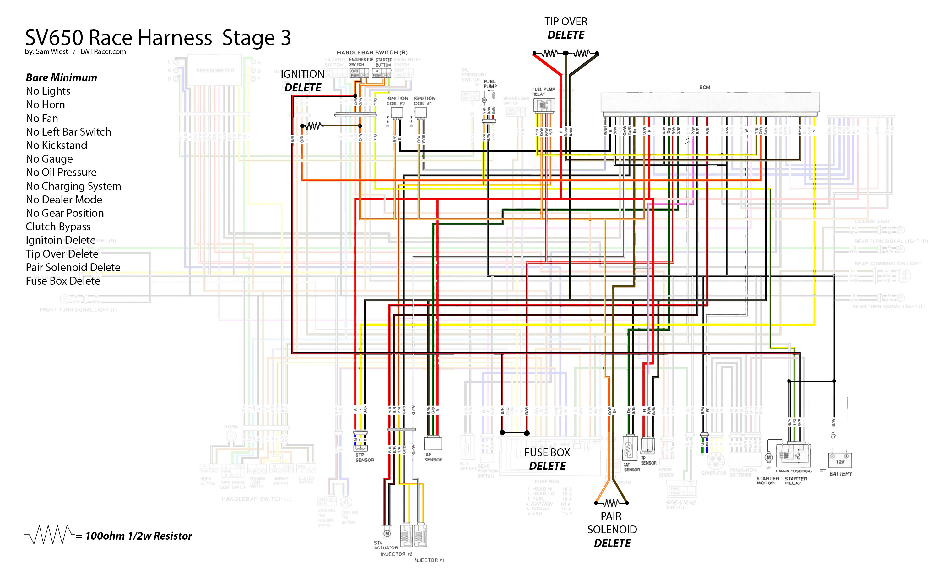
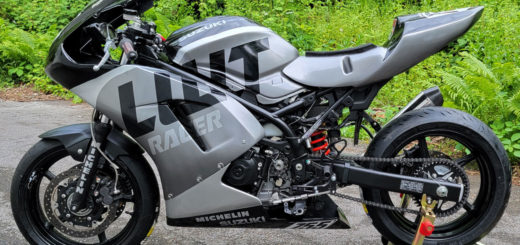
And if we are lucky enough to have finished this last diagram successfully, you should have a harness as simple as the one below.

SV650 Dealer Mode and Dealer Tuning
At the back of the harness you have a black connector and a white connector that are capped. If you are removing the OEM SV650 gauge cluster and do not plan on flashing your ECU, you can remove both of these. The white plug is to put the bike into dealer mode if you are throwing an FI light on the stock gauge. You can put your SV650 into dealer mode by bridging the White/Red wire with the Black/White wire. Take a short wire with both ends stripped and place each end into the connector to create the bridge between the W/R and B/W wire. This will show the codes up on the gauge cluster. Use the chart below to find out why your SV650 is a sad SV650.
| COO | None No defective part |
| C12 | Crankshaft position sensor (CKPS) |
| C13 | Intake air position sensor (ZAPS) |
| C14 | Throttle position sensor (TPS) |
| C15 | Engine coolant temperature sensor (ECTS) |
| C21 | Intake air temperature sensor (IATS) |
| C23 | Tip over sensor (TOS) |
| C24 | Ignition signal #1 |
| C25 | Ignition signal #2 |
| C28 | Secondary throttle valve actuator (STVA) |
| C29 | Secondary throttle position sensor (STPS) |
| C31 | Gear position signal (GP switch) |
| C32 | Fuel injector signal #1 |
| C33 | Fuel injector signal #2 |
| C41 | Fuel pump control system |
| C42 | Ignition switch signal |
| C49 | PAIR control solenoid valve |
| B/R (Black/Red Tracer) – Hot | B/W (Black/White Tracer) – Ground | B/Y (Black/Yellow Tracer) |
| Bl/B (Blue/Black Tracer) | O/W (Orange/White Tracer) | B/Bl (Black/Blue Tracer) |
| O/Bl (Orange/Blue Tracer) | O/B (Orange/Black Tracer) | G/Y (Green/Yellow Tracer) |
| Lg (Lightgreen) – RH Turn Signal | P (Pink) – Gear Position | Y (Yellow) – STP |
| W (white) – Crank Position/Headlight | B (Black) – Coil #2 | Br (Brown) |
| Gr (Gray) | O (Orange) | R (Red) |
| Lbl (Light blue) | Bl (Blue) – Neutral | G (Green) |
This post has already been read 60616 times!